GE90 High Bypass Turbofan Engine
Overview
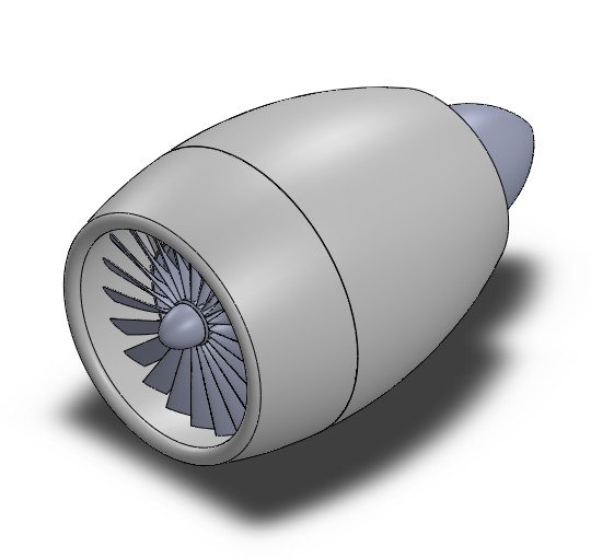
This project involved reverse-engineering and modeling the General Electric GE90-115B, a pinnacle of aerospace engineering. The objective was to create a high-fidelity mechanical assembly that replicates the internal flow path and the iconic "S-shape" composite fan blades, while ensuring all components adhere to realistic structural and aerodynamic constraints.
Internal Components & Spool Architecture
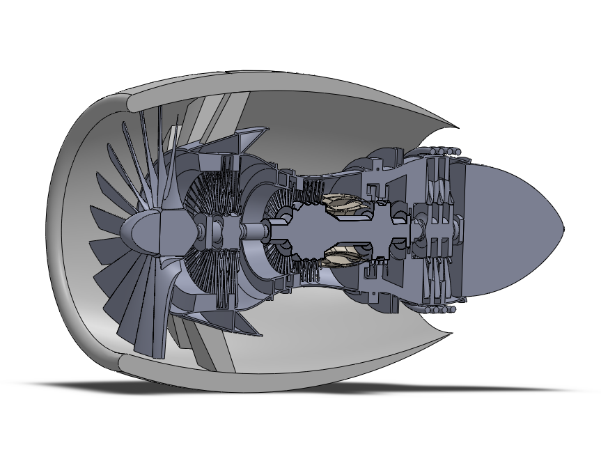
The GE90 utilizes a dual-spool architecture, which I replicated through a complex system of concentric shafts and rotating stages. This mechanical separation allows the high-pressure and low-pressure sections to operate at their respective optimal rotational speeds, a critical requirement for high-bypass efficiency.
- Low-Pressure (LP) Spool: Consists of the massive 128-inch front fan and 3-stage booster compressor, driven by a 6-stage low-pressure turbine. The LP shaft runs through the center of the HP shaft, requiring precise concentric mating and clearance management in SolidWorks.
- High-Pressure (HP) Spool: Features a 6-stage high-pressure compressor (HPC) driven by a 3-stage high-pressure turbine. This "core" of the engine is responsible for the massive compression ratios required for high-energy combustion.
- Combustion Chamber: Architected as an annular bridge between the HPC and HPT, including modeled fuel injector ports and internal cooling vents to simulate realistic thermal flow paths.
Parametric Blade Geometry
The 22 signature fan blades were modeled using parametric spline equations in SolidWorks to capture the complex sinusoidal twist required for subsonic efficiency. By utilizing advanced surfacing techniques—specifically lofts and boundary surfaces—the geometry transitions seamlessly from the hub to the blade tip, maintaining aerodynamic continuity.
Core Integration & Analysis
Beyond visual modeling, the project focused on mechanical validation. I designed a functional core flow path featuring a 10-stage high-pressure compressor (HPC), an annular combustion chamber with integrated swirler ports, and multi-stage turbines. Using SolidWorks Simulation, I performed preliminary assessments to ensure the assembly could support the physics of flight:
- Mechanical Coupling: Modeled a dual-spool system with high-pressure and low-pressure shafts rotating independently with precise concentric mating.
- Structural Validation (FEA): Conducted static studies to monitor Von Mises stress levels on the rotating turbine stages, ensuring structural integrity under simulated 5,000 RPM centrifugal loads.
Software & Workflow
The entire assembly was managed using Top-Down design principles in SolidWorks. Master skeleton sketches were used to drive global variables, allowing for rapid iteration of stage counts and blade pitches. This structured workflow was essential for maintaining performance across a large assembly and ensuring zero-interference between stationary stators and rotating components.
Mechatronics Considerations
As a Mechatronics project, emphasis was placed on the "System" view. The design accounts for the integration of sensors (bleed air ports) and mechanical power extraction for the accessory gearbox. The project served as a case study in managing 100+ part hierarchies and utilizing advanced CAD features to simulate real-world aerospace hardware.